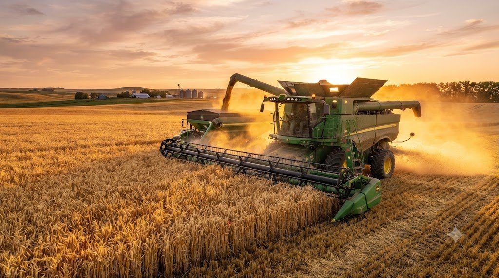
Harvesting agricultural grain crops represents the culmination of a full growing season’s labor, capital investment, and agronomic management. In modern broadacre farming, the combine harvester is the ultimate multi-stage mechanical processing plant on wheels, performing cutting, feeding, threshing, separating, cleaning, and material handling in a continuous, high-speed single pass across the field. Among these interconnected processes, threshing and separation constitute the critical mechanical boundary where economic yield is either captured into the clean grain tank or permanently lost out the rear of the machine. Understanding the physics governing crop mat feeding, rotor dynamics, concave clearance tolerances, and centrifugal separation mechanics is essential for harvesters striving to minimize rotor losses while preserving seed embryo viability and grain quality.
1. Crop Feeding Dynamics: Feeder House Mechanics and Stone Trap Protection
Effective grain threshing begins well before crop material reaches the spinning threshing rotor. The feeder house serves as the critical intake elevator, accepting cut crop material delivered by the header auger or draper center belts and accelerating it upward into the threshing chamber in a uniform, compressed mat.
A modern high-capacity feeder house utilizes heavy-duty multi-strand roller chains linked by serrated steel slats. Chain tension must be calibrated precisely using hydraulic or spring-loaded take-up bolts. If the chain is loose, slats deflect under heavy slugs of damp straw, causing uneven bunching and feeding hesitation; if excessively tight, chain bushings suffer accelerated wear and impose parasitic drag on feeder drive gearboxes.
Directly behind the upper feeder house drum sits the stone trap—a deep transverse trough equipped with a heavy spring-loaded hinged door. As crop material is accelerated toward the rotor feed accelerator, dense foreign objects such as rocks, iron fence debris, and hardened root balls are propelled downward by kinetic momentum into the stone trap rather than entering the rotor cage. Daily manual emptying and inspection of the stone trap prevents catastrophic rotor rasp bar bending and concave destruction.
When encountering an unexpected feeder house slug or slug stall, never attempt to force material through by slipping the main engine clutch. Engage the heavy-duty hydraulic or planetary feeder reverser immediately to back the compressed crop plug onto the header table, allowing the operator to inspect feed conditions safely before resuming forward travel.
2. Evolution of Threshing: Conventional Tangential Cylinders vs. Axial-Flow Rotors
For decades, conventional combines utilized a transverse, tangential threshing cylinder rotating over a semicircular concave grate, followed by long oscillating straw walkers to separate residual grain from the straw mat. While gentle on straw integrity, conventional systems face severe throughput limits because crop material passes through the threshing zone in a single rapid arc lasting fractions of a second.
Modern high-capacity combines predominantly feature Axial-Flow or Rotary threshing architectures. In an axial system, the threshing rotor is positioned longitudinally along the machine’s axis of travel. The crop stream enters the conical front inlet of the rotor housing and is guided rearward in a multi-pass helical spiral by directional vanes bolted to the upper rotor cage cover.
Instead of a single violent impact stroke, axial rotors subject the crop mat to multiple gentle rubbing passes across the concaves over several complete rotations. This extended dwell time achieves two profound operational advantages:
- Reduced Grain Damage: Rubbing grain-on-grain rather than steel-on-grain dramatically decreases cracked kernels, broken seed coats, and split beans, preserving germination rates in certified seed production and maintaining premium milling grades.
- Surge Capacity: The massive surface area of a 30-inch-diameter rotor provides tremendous throughput capacity, allowing modern Class 8 to Class 10 combines to harvest over 80 to 120 metric tons of wheat or corn per hour without choking.
| Combine Architecture | Threshing Method | Separation Principle | Grain Damage Potential | Throughput Limit (Tons/Hr) |
|---|---|---|---|---|
| Conventional Tangential | Transverse cylinder + concave | Oscillating straw walkers (gravity) | Moderate to High at high rpm | 35 – 55 Tons/Hr |
| Hybrid (Cylinder + Twin Rotors) | Transverse accelerator + twin rotors | Centrifugal rotor separation grates | Low to Moderate | 65 – 95 Tons/Hr |
| Single Axial Rotor | Longitudinal single large rotor | Centrifugal helical multi-pass | Very Low (grain-on-grain rub) | 75 – 115 Tons/Hr |
| Twin Axial Rotors | Dual longitudinal counter-rotating rotors | Centrifugal helical multi-pass | Minimal grain crack risk | 85 – 130 Tons/Hr |
3. Rotor Rasp Bar Geometry and Concave Clearance Calibration
The mechanical heart of the axial threshing chamber consists of hardened steel rasp bars mounted in staggered chevron patterns along the front threshing section of the rotor. Rasp bars feature directional diagonal serrations that grab the crop stream, accelerating it against the stationary curved concave grates located below.
Concave clearance—the physical radial distance between the spinning rasp bar tips and the inner face of the concave wires—is the single most sensitive operational setting on a combine harvester. Concave clearance dictates the degree of physical compression exerted upon the passing crop mat:
Excessively Tight Concave Clearance
When concaves are set too tight, grain kernels are subjected to intense mechanical shearing forces, leading to cracked kernels, chipped germ ends, and excessive pulverization of straw. Over-pulverized straw breaks into fine chaff particles that severely overload the lower cleaning shoe, blowing clean grain out the rear of the machine.
Excessively Wide Concave Clearance
Conversely, if concave clearance is too wide, crop material passes through without sufficient frictional rubbing. Grain remains trapped inside unthreshed pods, wheat glumes, or corn cobs, resulting in unthreshed grain passing directly into the chopper and spilling onto the ground as unharvested field loss.
Before each harvest season, perform a physical concave zero-point leveling calibration. Use a feeler gauge or steel gauge block to verify that front and rear clearances match across left, center, and right quadrants. An out-of-level concave creates an uneven threshing gap that causes simultaneous grain cracking on one side and unthreshed grain losses on the other.
4. Centrifugal Separation Mechanics and Rotor Cage Vane Angles
Once grain is threshed free from its protective husks, it must be rapidly separated from the dense volume of straw and stalks before the residue is ejected from the rear of the rotor. In axial combines, this separation is mediated by Centrifugal Force.
As the rotor spins at speeds between 250 and 1,100 rpm (depending on crop type), centrifugal acceleration forces dense, heavy grain kernels outward toward the perimeter of the rotor cage. The lighter, bulky straw remains suspended along the inner rotor core. Grain kernels pass through open finger grates or separator grates in the lower half of the cage, falling onto the grain pan or clean grain auger bed below.
The speed at which the crop mat spirals rearward through the separation chamber is governed by the pitch angle of the adjustable transport vanes mounted along the top cage cover. In dry, brittle crops where grain separates easily, advancing the vanes to a fast pitch accelerates crop exit, saving fuel and reducing straw breakdown. In tough, damp, green-stem soybeans or high-moisture wheat, retarding the vane pitch slows crop travel, keeping material in the separation zone for extra revolutions to ensure complete grain extraction.
5. Threshing Parameters Across Major Crop Species
Different grain crops exhibit radically divergent physical characteristics, requiring customized rotor speeds, concave configurations, and module selections:
- Corn / Maize (Zea mays): Requires round-bar concaves with large clearances (25 to 35 mm) and low rotor speeds (280 to 450 rpm) to gently rub kernels off the cob without splintering the moist core into debris that blinds the cleaning sieves.
- Wheat and Barley (Triticum aestivum): Requires small-wire or narrow-spaced concaves with tight clearances (6 to 14 mm) and high rotor speeds (750 to 980 rpm) to vigorously shatter tough glumes and separate awns.
- Soybeans (Glycine max): Demands round-bar or wide-wire concaves set at 15 to 22 mm with moderate rotor speeds (400 to 600 rpm) to pop open pods without splitting fragile, dry bean halves.
- Canola / Rapeseed (Brassica napus): Highly sensitive to over-threshing. Requires smooth filler plates inserted into front concaves, wide clearance (18 to 26 mm), and reduced rotor speed (350 to 500 rpm) to avoid pulverizing green stems into high-moisture sap cakes.
6. Variable-Speed Rotor Drives: Hydraulic vs. Variable Belt Sheaves
Maintaining constant rotor speed regardless of fluctuating crop intake volumes is vital for uniform threshing. Combines employ one of two primary drive mechanisms to transmit engine power to the heavy rotor:
Variable-Pitch Mechanical Sheaves (Posischeave Drives)
A heavy, multi-groove drive belt runs between hydraulically modulated variable-pitch sheaves. Expanding or contracting the sheave halves alters the effective drive belt diameter, varying rotor speed smoothly from the cab. While mechanically robust, belt slip can occur during massive slug overloads, requiring spring-loaded belt tension monitors to prevent belt glazing and thermal failure.
Hydrostatic and Planetary Planetary-Hydraulic Drives
Modern flagship combines feature planetary gearboxes coupled with closed-loop hydrostatic motor circuits to drive the rotor. This design provides infinite speed control under load, eliminates heavy drive belts, and allows reversible rotation—enabling the operator to rock a stalled rotor backward with high hydraulic torque from an in-cab switch to clear severe blockages in seconds.
7. Residue Management: Straw Choppers, Chaff Spreaders, and Soil Tilth
After grain separation is complete, the remaining straw and chaff residue must be processed and redistributed across the harvested field to facilitate no-till or reduced-till planting in the subsequent season. An uneven windrow of thick straw shields soil from sunlight, retards spring soil warming, and creates physical blockages for precision seed drill coulters.
Modern combines feature integrated high-speed straw choppers equipped with 64 to over 100 reversible carbide-coated rotating hammer knives intermeshing with stationary counter-knives. Spinning at over 3,000 rpm, the chopper pulverizes tough wheat straw and corn stalks into short 2-to-4-inch fragments. Dual hydraulic or electric directional tailboard spinners or active power-cast deflectors broadcast this residue uniformly across the full width of modern 45-foot draper headers, ensuring balanced soil organic matter distribution.
8. Preventative Maintenance and Threshing Component Longevity
Abrasive silica in crop dust, combined with intense mechanical rubbing friction, causes inevitable wear across all threshing components. Technicians must conduct rigorous inspections throughout the harvest cycle:
- Rasp Bar Leading Edge Wear: Inspect rasp bars every 150 hours. Once the leading serration edge rounds off beyond a 3-millimeter radius, the bar begins pushing rather than grabbing crop, causing unthreshed heads and increasing rotor drive horsepower draw by up to 25%.
- Rotor Dynamic Balancing: When replacing worn rasp bars, always replace them in matched opposing pairs directly across the rotor diameter. An unbalanced rotor spinning at 900 rpm induces violent harmonic vibrations that destroy main rotor support bearings and fatigue chassis structural welds.
- Concave Wire Integrity: Check concave wires for bowed or missing sections caused by rock impacts. Missing wires allow unthreshed pods to pass directly into the clean grain system without adequate threshing.
- Rotor Bearing Greasing and Temperature Auditing: Lubricate main front and rear rotor bearings daily using high-temp synthetic polyurea grease. Use an infrared pyrometer to audit bearing temperatures during fuel stops; any bearing running 25°C hotter than ambient baseline indicates imminent internal roller cage failure.
9. Rotor Power Loss Diagnostics and Slug Reversal Dynamics
Even the most skilled combine operator will occasionally encounter tough field conditions—such as green-stem soybeans or damp lodged wheat swaths—that produce sudden crop slugging inside the rotor cage. Recognizing the thermodynamic and mechanical indicators of impending rotor blockage is essential to protect heavy drivelines from catastrophic failure.
When an excessive slug of damp crop material enters the threshing cone, the immediate mechanical indicator is a rapid surge in engine load percentage accompanied by a sharp drop in rotor rpm. Modern combines feature automatic feed rate control systems (such as HarvestSmart™ or CEMOS Automatic™) that continuously monitor engine torque reserve, hydrostatic drive pressure, and rotor drive belt slip. If rotor speed drops by more than 5% below its commanded setpoint, the system autonomously decelerates the combine’s forward ground speed to prevent a complete rotor stall.
If a total rotor stall occurs, operators must follow a disciplined clearance procedure: immediately disengage the main separator clutch, lower engine rpm to idle, and activate the hydraulic or planetary rotor reverser. The reverser exerts tremendous mechanical torque at low speed, rocking the rotor backward through a 45-degree arc to unwedge the compressed crop plug against the concave grates, allowing the slug to be cleared through the feeder house without requiring manual hand-wrenching.
10. Pre-Harvest Concave and Rotor Balancing Protocols
Achieving peak threshing performance demands thorough mechanical preparation before the harvest season commences:
- Feeler Gauge Concave Parallelism Verification: Use a precision steel measuring wedge to measure the clearance between the rotor rasp bar tips and concave crossbars at the front, middle, and rear sections on both left and right sides. Any side-to-side variation exceeding 1.5 mm must be corrected by adjusting the eccentric concave leveling turnbuckles.
- Rasp Bar Serration Sharpness Audit: Check the leading edge profile of every rasp bar. If the leading square edge has rounded off by more than 3 millimeters, replace the rasp bars in complete matched sets. Rounded bars generate excessive frictional heat and crack fragile grain embryos.
- Discharge Beater Paddle Inspection: Inspect the chevron paddle wear plates on the rear discharge beater drum. The beater must cleanly strip exiting straw from the rear rotor cone; worn beater paddles allow straw to wrap around the rear rotor shaft, generating dangerous friction heat that can ignite harvest dust fires.


